Wheel Speed Sensor Replacement Left Front
Removal Procedure
- Raise and support the vehicle on a suitable hoist. Refer to Lifting and Jacking the Vehicle in General Information.
- Remove the left front tire and wheel assembly. Refer to Tire and Wheel Removal and Installation in Tires and Wheels.
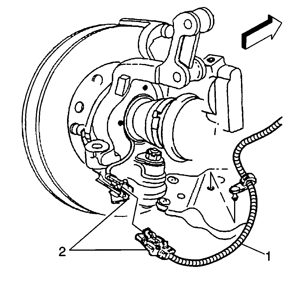
- Remove the left front wheel speed sensor electrical connector (1).
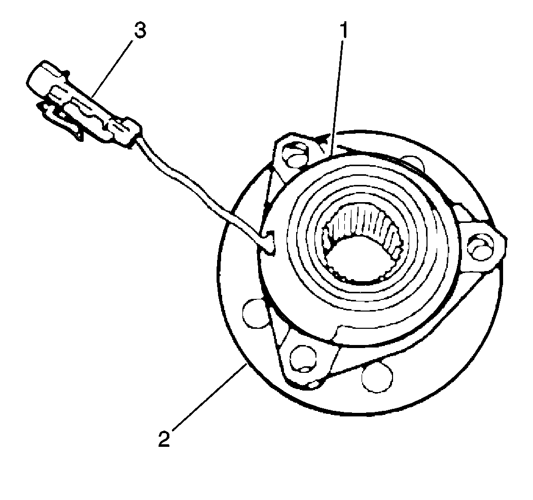
- Remove the hub and bearing assembly (2). Refer to Front Suspension in Suspension.
- Use a blunt screwdriver to remove the left wheel speed sensor (1) from the hub and bearing assembly (2).
- Inspect the bearing for signs of water intrusion. Replace the bearing if water intrusion exists.
Important: The left front sensor is serviceable only as an assembly. Do not service the harness pigtail individually because the harness pigtail is part of the sensor.


Important: When the wheel speed sensor is removed, it must be replaced. The wheel speed sensor is damaged when it is removed and cannot be reused. Replace the two components of the wheel speed sensor as an assembly. The two components of the wheel speed sensor cannot be replaced individually.
Installation Procedure
Tools Required
J 38764-1A Wheel Speed Sensor Installation Kit
- Apply LOCTITE™ 620 to the mating surfaces of the wheel speed sensor (1) that contact the hub and bearing assembly (2).
- Use a J 38764-1A with an arbor type press in order to install the left front wheel speed sensor (1) onto the hub and bearing assembly (2).
- Install the hub and bearing assembly (2) to the vehicle. Refer to Front Suspension in Suspension.
- Install the front wheel speed sensor electrical connector (2).
- Install the wheel and tire assembly. Refer to Tire and Wheel Removal and Installation in Tires and Wheels.
- Lower the vehicle.


Wheel Speed Sensor Replacement Right Front
Removal Procedure
- Raise and support the vehicle on a suitable hoist. Refer to Lifting and Jacking the Vehicle in General Information.
- Remove the right front tire and wheel assembly. Refer to Tire and Wheel Removal and Installation in Tires and Wheels.
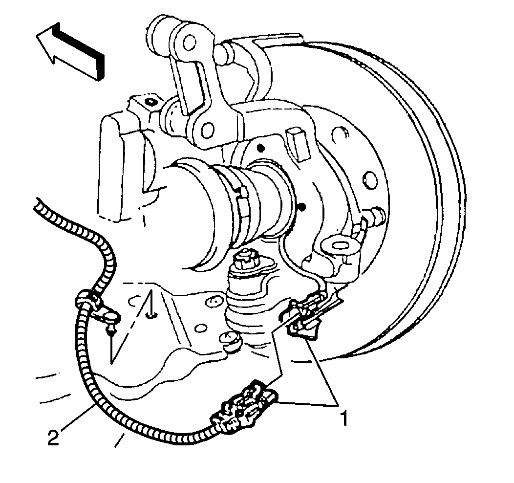
- Remove the right front wheel speed sensor electrical connector (1).
- Remove the hub and bearing assembly (2). Refer to Front Suspension in Suspension.
- Use a blunt screwdriver to remove the right front wheel speed sensor (1) from the hub and bearing assembly (2).
- Inspect the bearing for signs of water intrusion. Replace the bearing if water intrusion exists.
Important: The front sensor is serviceable only as an assembly. Do not service the harness pigtail individually because the harness pigtail is part of the sensor.


Important: When the wheel speed sensor is removed, it must be replaced. The wheel speed sensor is damaged when it is removed and cannot be reused. Replace the two components of the wheel speed sensor as an assembly. The two components of the wheel speed sensor cannot be replaced individually.
Installation Procedure
Tools Required
J 38764-1A Wheel Speed Sensor Installation Kit
- Apply LOCTITE™ 620 to the mating surfaces of the right front wheel speed sensor (1) that contact the hub and bearing assembly (2).
- Use a J 38764-1A with an arbor type press to install the right front wheel speed sensor (1) onto the hub and bearing assembly (2).
- Install the hub and bearing assembly to the vehicle. Refer to Front Suspension in Suspension.
- Install the right front wheel speed sensor electrical connector (1).
- Install the right front wheel and tire assembly. Refer to Tire and Wheel Removal and Installation in Tires and Wheels.
- Lower the vehicle.


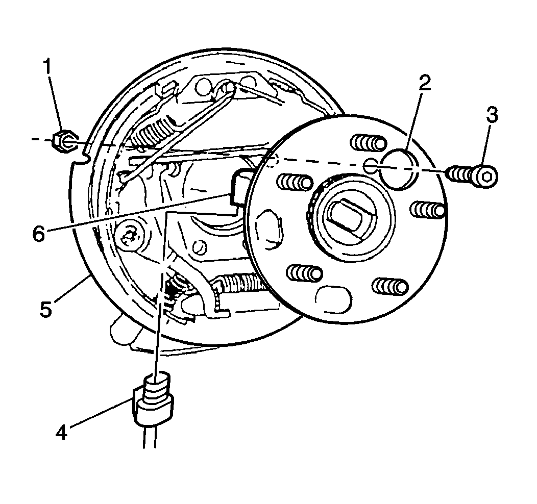
Wheel Speed Sensor Replacement Rear Wheel Bearing/Sensor

