Tools Required
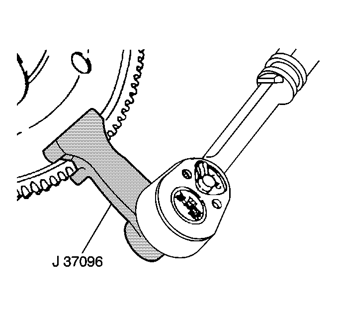
| • | J 37096 Flywheel Holder |
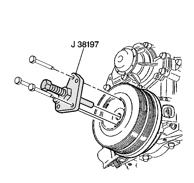
| • | J 38197-A Crankshaft Balancer Remover |
| • | J 45059 Electronic Torque Angle Meter |
Removal Procedure
- Disconnect the negative battery cable. Refer to Battery Negative Cable Disconnection and Connection .
- Remove the drive belt. Refer to Drive Belt Replacement .
- Raise and support the vehicle. Refer to Lifting and Jacking the Vehicle .
- Remove the right front tire and wheel. Refer to Tire and Wheel Removal and Installation .
- Remove the right engine splash shield retainers and the engine splash shield.
- Remove the torque converter covers. Refer to Torque Converter Cover Replacement .
- Use the J 37096 to secure the flywheel in order to prevent the crankshaft from rotating.
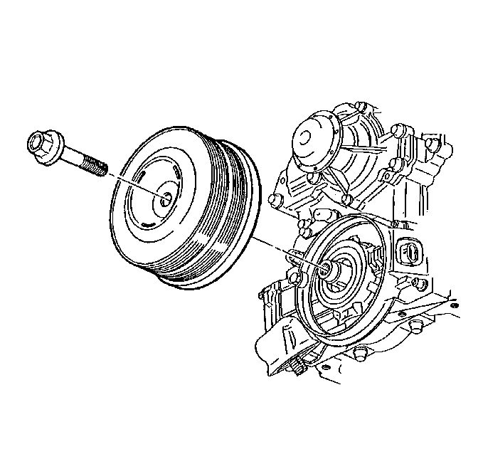
- Remove the crankshaft balancer bolt and discard the balancer bolt.
- Install the J 38197-A .
- Remove the crankshaft balancer.
- Remove the J 38197-A .
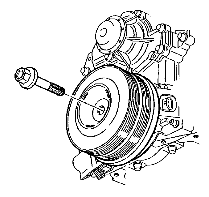
Important: Do not separate the crankshaft pulley from the crankshaft balancer. Service the crankshaft pulley and the crankshaft balancer as an assembly.
Installation Procedure
- Coat the engine front cover seal contact area on the crankshaft balancer, and the seal surface with engine oil.
- Install the crankshaft balancer.
- Use the J 37096 to secure the flywheel in order to prevent the crankshaft from rotating.
- Install the new crankshaft balancer bolt.
- Tighten the bolt to 150 N·m (111 lb ft).
- Use the J 45059 to rotate the bolt an additional 76 degrees.
- Remove the J 37096 .
- Install the torque converter covers. Refer to Torque Converter Cover Replacement .
- Install the right engine splash shield and the engine splash shield retainers.
- Install the right front tire and wheel. Refer to Tire and Wheel Removal and Installation .
- Lower the vehicle.
- Install the drive belt. Refer to Drive Belt Replacement .
- Perform the CKP system variation learn procedure. Refer to Crankshaft Position System Variation Learn .
Notice: Use the correct fastener in the correct location. Replacement fasteners must be the correct part number for that application. Fasteners requiring replacement or fasteners requiring the use of thread locking compound or sealant are identified in the service procedure. Do not use paints, lubricants, or corrosion inhibitors on fasteners or fastener joint surfaces unless specified. These coatings affect fastener torque and joint clamping force and may damage the fastener. Use the correct tightening sequence and specifications when installing fasteners in order to avoid damage to parts and systems.
Tighten
