GM Service Manual Online
For 1990-2009 cars only
Figure 1:

Module Power, Ground, Serial Data, and MIL
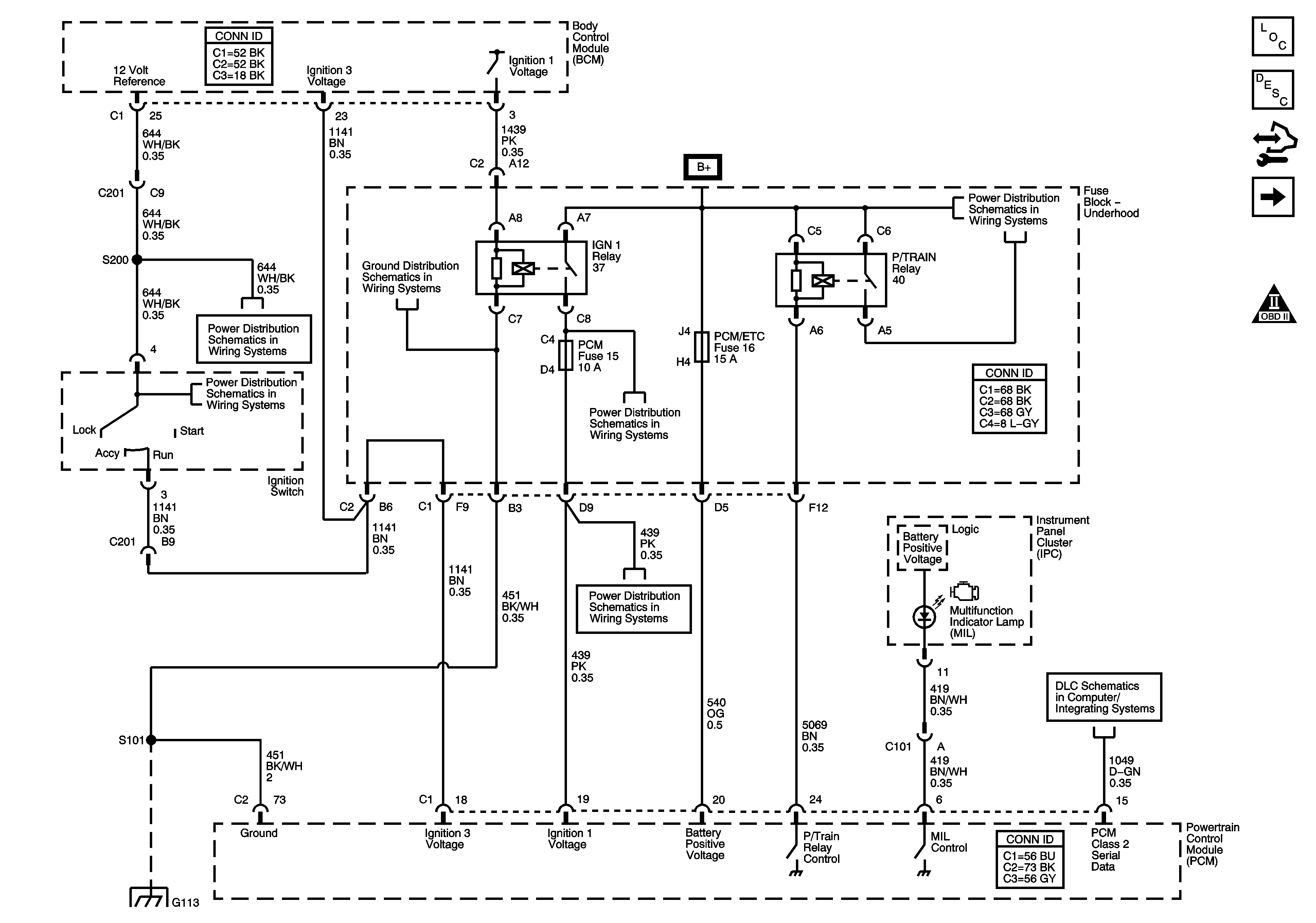

Object Number: 1645566  Size: FS
Master Electrical Component List
Powertrain Control Module Description
Control Module References
5 Volt and Low Reference
Engine Controls Schematic Icons
Ignition Switch
Ignition Switch
G101, G102, G103, G111, G112, and G113
Fuse Block - Underhood ABS, TRANS SOL, PCM, SIR, and DISPLAY Fuses, CRANK Relay, and Fuse Block - I/P CRUISE SW Fuse
Fuse Block - Underhood B+ Bus
G101, G102, G103, G111, G112, and G113
Data Link Connector (DLC) Schematics L26
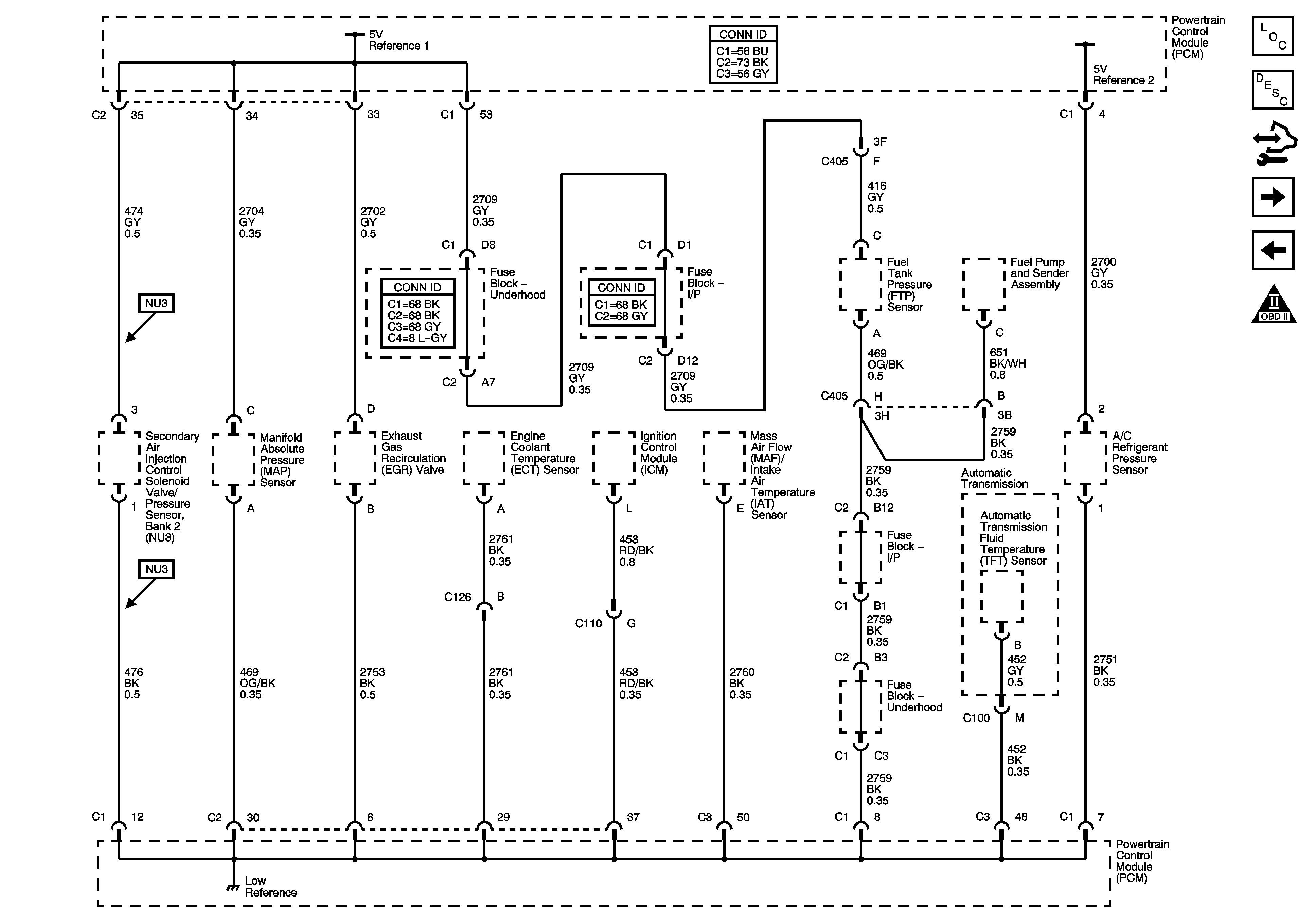
Figure 2:

5-Volt and Low Reference


Object Number: 1645567  Size: FS
Master Electrical Component List
Powertrain Control Module Description
Control Module References
Pressure and Temperature Sensors
Module Power, Ground, Serial Data, and MIL
Engine Controls Schematic Icons
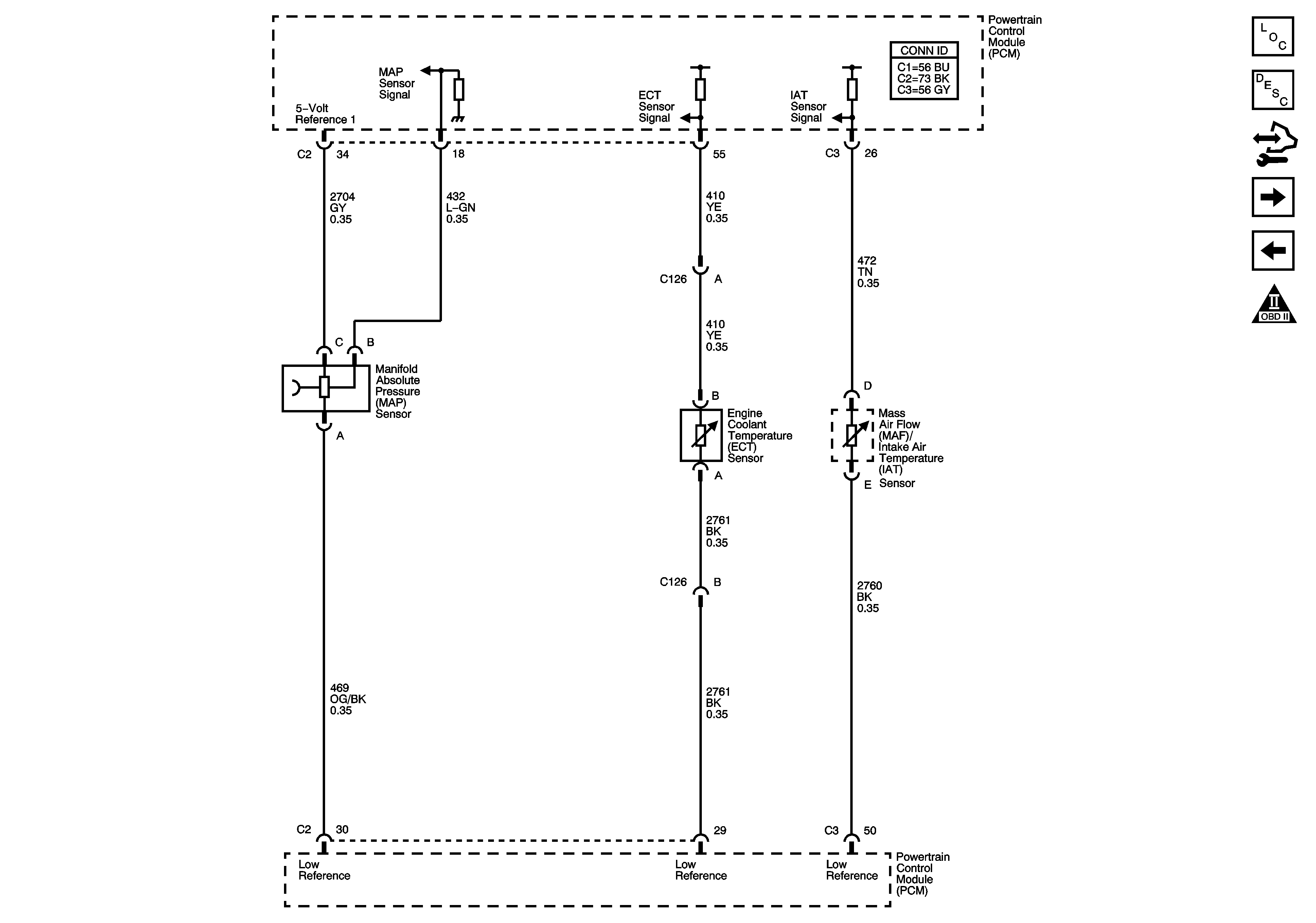
Figure 3:

Pressure and Temperature Sensors


Object Number: 1645574  Size: FS
Master Electrical Component List
Powertrain Control Module Description
Control Module References
MAF, VSS
5 Volt and Low Reference
Engine Controls Schematic Icons
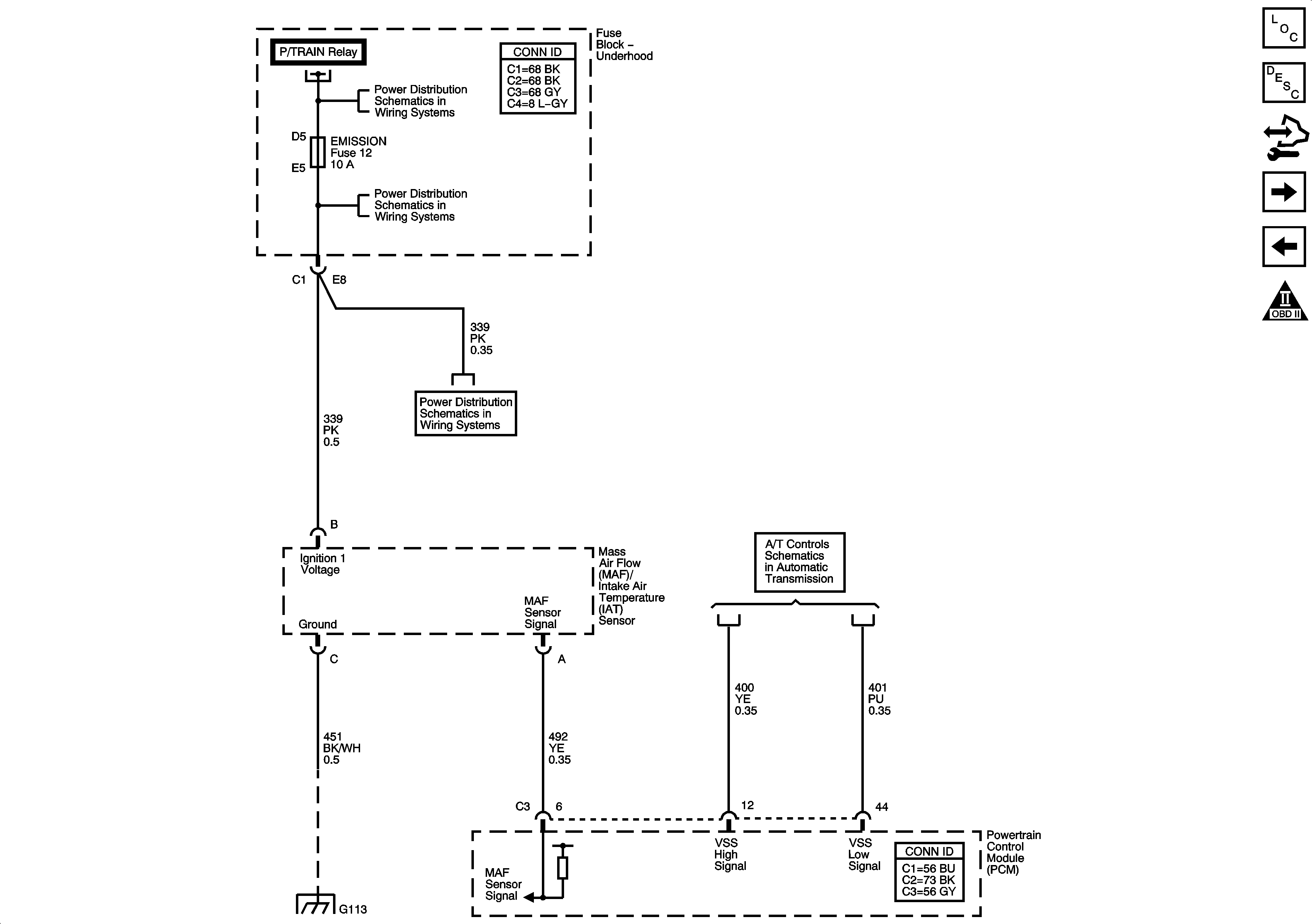
Figure 4:

MAF, VSS


Object Number: 1645581  Size: FS
Master Electrical Component List
Powertrain Control Module Description
Control Module References
Oxygen Sensors
Pressure and Temperature Sensors
Engine Controls Schematic Icons
Fuse Block - Underhood ETC, ELEK IGN (L26), FUEL INJ (L26), 02 SSR (L26), and EMISSION Fuses
PC Solenoid Valve, Fluid Pressure Manual Valve Position Switch, ISS and VSS SEnsors (L26)
G101, G102, G103, G111, G112, and G113
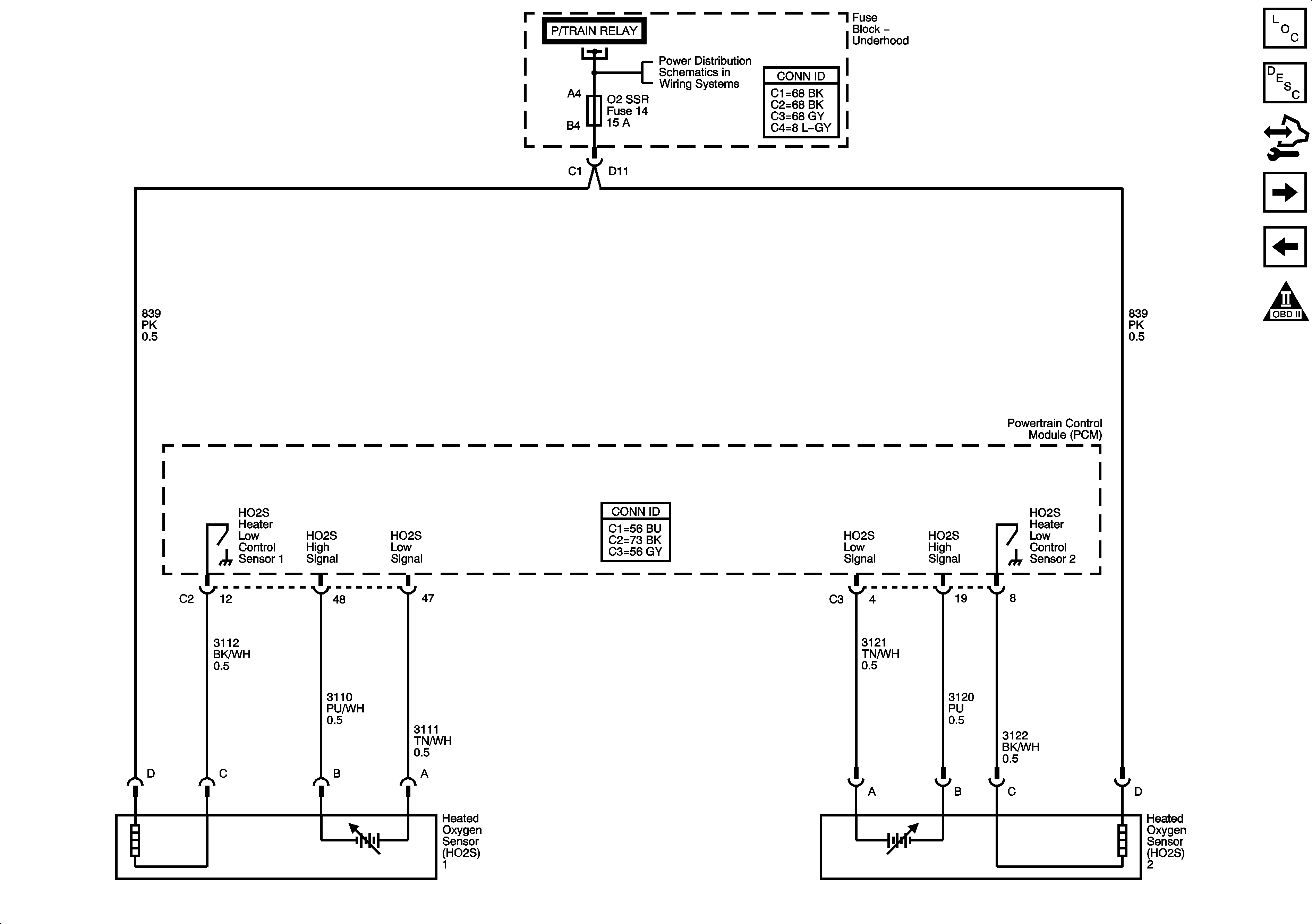
Figure 5:

Oxygen Sensors


Object Number: 1645577  Size: FS
Master Electrical Component List
Powertrain Control Module Description
Control Module References
Electronic Throttle Controls
MAF, VSS
Engine Controls Schematic Icons
Fuse Block - Underhood B+ Bus
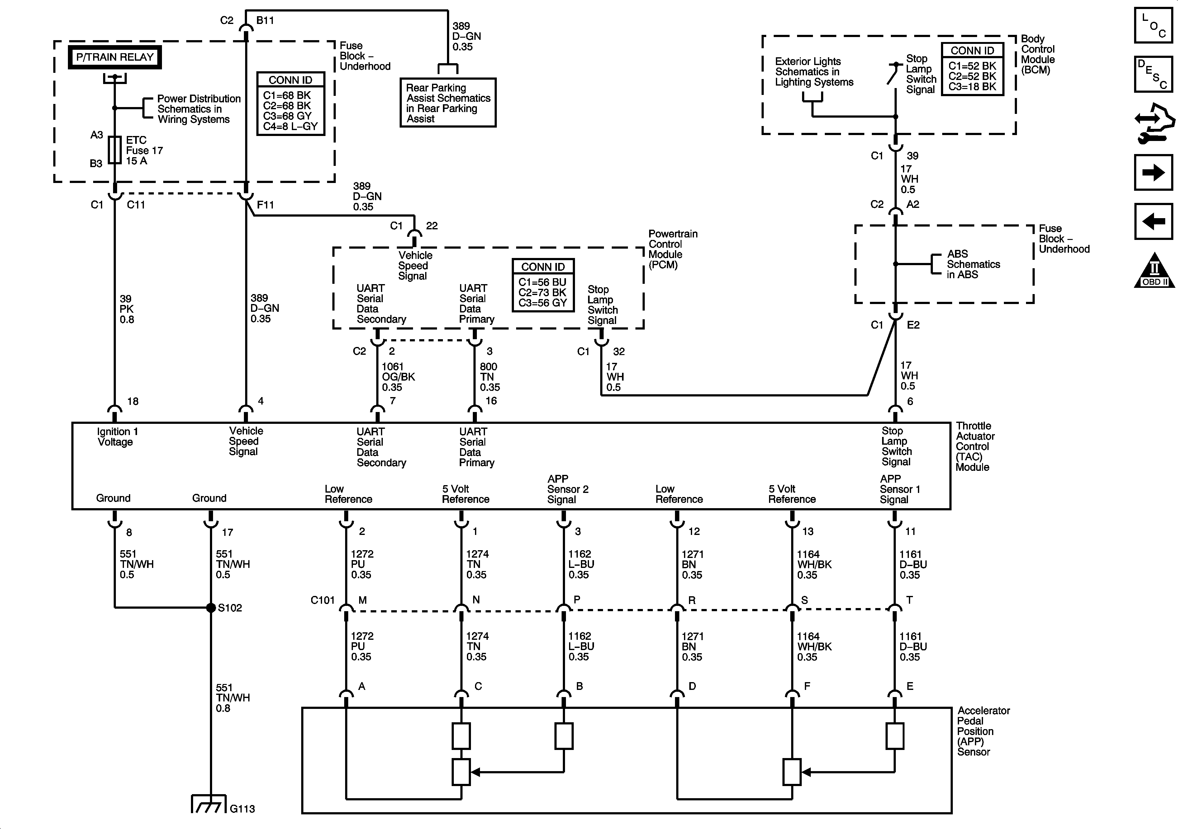
Figure 6:

Electronic Throttle Controls


Object Number: 1645582  Size: FS
Master Electrical Component List
Throttle Actuator Control (TAC) System Description
Control Module References
Ignition Controls
Oxygen Sensors
Engine Controls Schematic Icons
Fuse Block - Underhood B+ Bus
Object Detection Schematics
Turn Signal, Hazard and Stop Lamps Outputs
Data Active Brake and Stability
G101, G102, G103, G111, G112, and G113
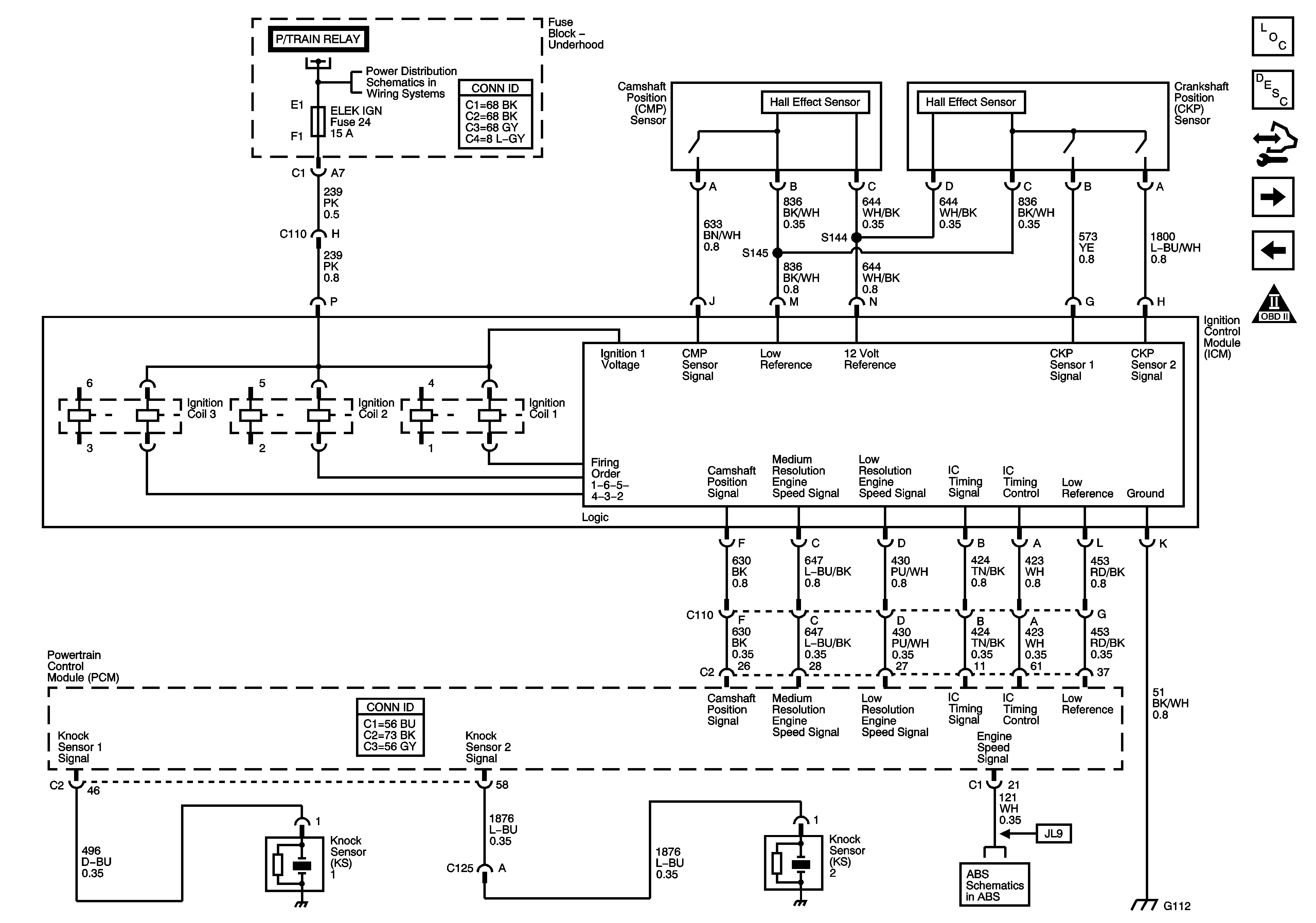
Figure 7:

Ignition Controls


Object Number: 1645583  Size: FS
Master Electrical Component List
Electronic Ignition (EI) System Description
Control Module References
Fuel Pump Controls
Electronic Throttle Controls
Engine Controls Schematic Icons
Fuse Block - Underhood B+ Bus
Data Active Brake and Stability
G101, G102, G103, G111, G112, and G113
Figure 8:

Fuel Pump Controls


Object Number: 1645586  Size: FS
Master Electrical Component List
Fuel System Description
Control Module References
Fuel Injectors
Ignition Controls
Engine Controls Schematic Icons
Fuse Block - Underhood B+ Bus
G101, G102, G103, G111, G112, and G113
Power, Ground, Serial Data, and Gages L26
G302
G101, G102, G103, G111, G112, and G113
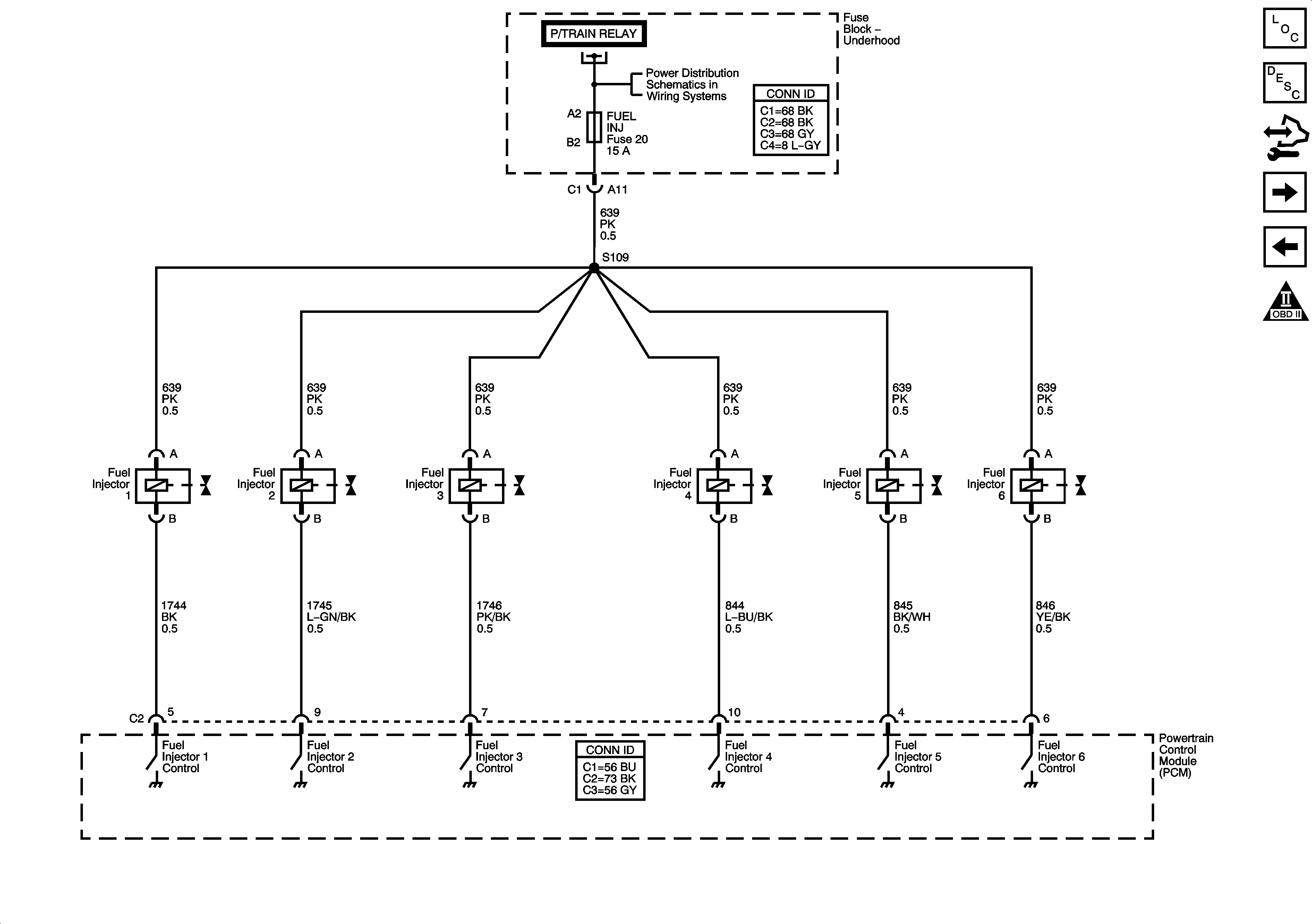
Figure 9:

Fuel Injectors


Object Number: 1645587  Size: FS
Master Electrical Component List
Fuel System Description
Control Module References
EVAP, EGR, and FTP Controls
Fuel Pump Controls
Engine Controls Schematic Icons
Fuse Block - Underhood B+ Bus
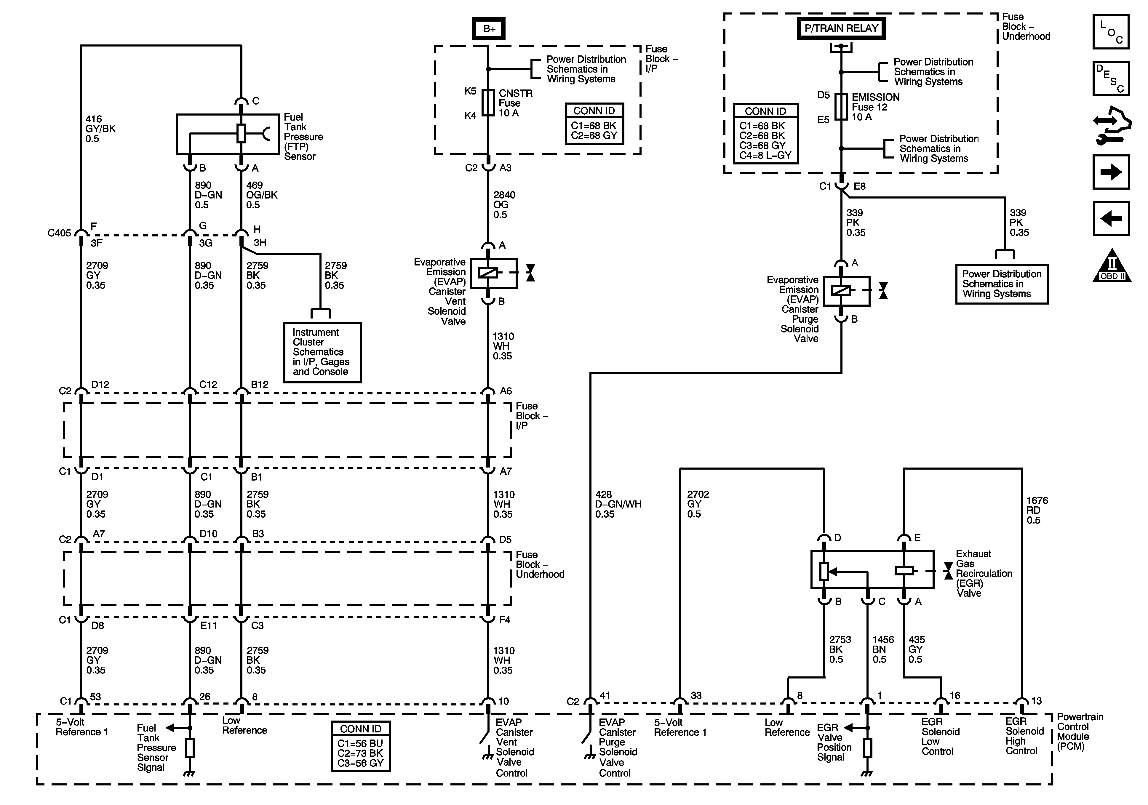
Figure 10:

EVAP, EGR, and FTP Controls


Object Number: 1645588  Size: FS
Master Electrical Component List
Exhaust Gas Recirculation (EGR) System Description
Control Module References
AIR Controls (NU3)
Fuel Injectors
Engine Controls Schematic Icons
Fuse Block - Underhood B+ Bus
Fuse Block - Underhood ETC, ELEK IGN (L26), FUEL INJ (L26), 02 SSR (L26), and EMISSION Fuses
Power, Ground, Serial Data, and Gages L26
Fuse Block - Underhood ETC, ELEK IGN (L26), FUEL INJ (L26), 02 SSR (L26), and EMISSION Fuses
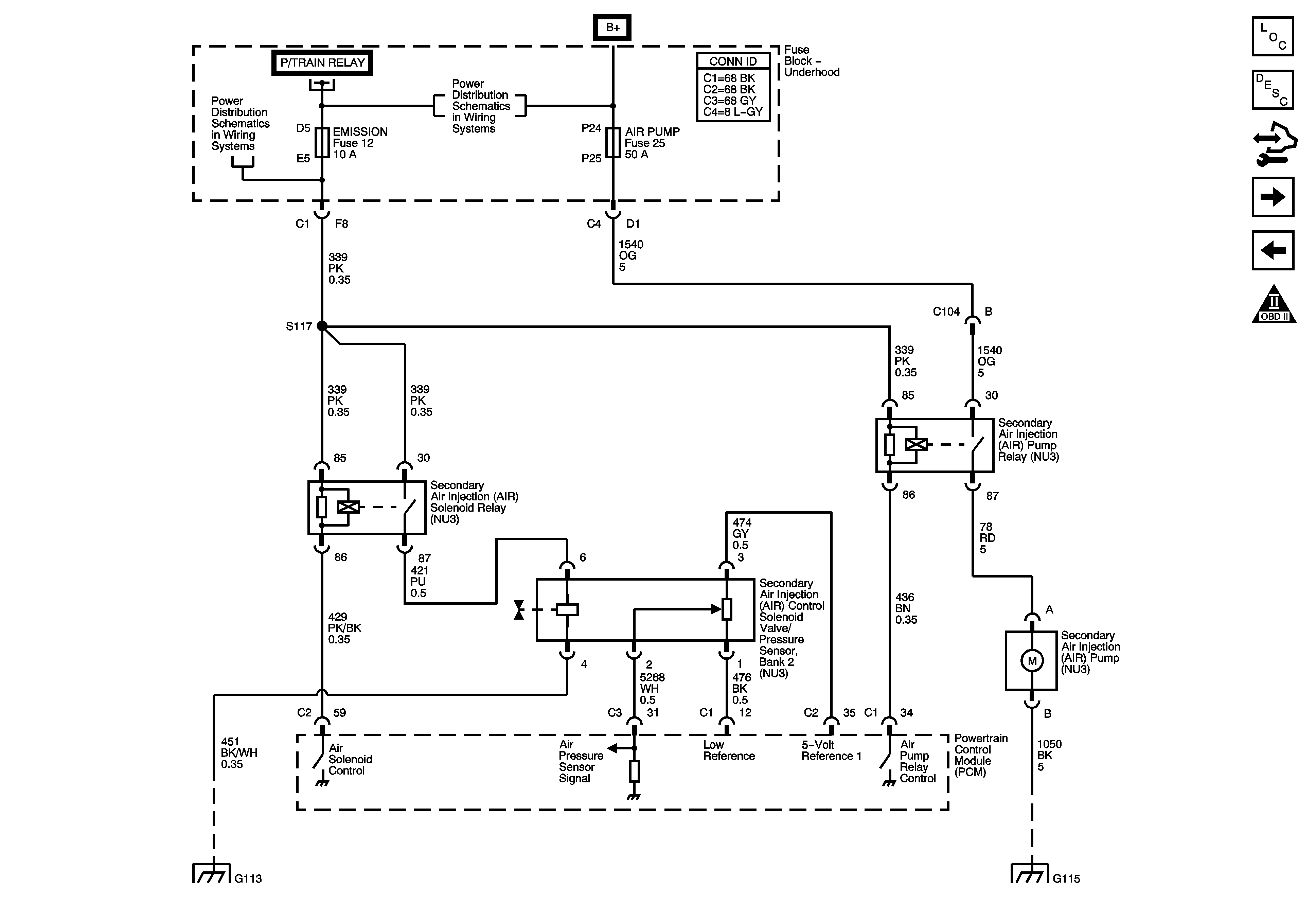
Figure 11:

AIR Controls (NU3)


Object Number: 1645589  Size: FS
Master Electrical Component List
Secondary Air Injection System Description
Control Module References
Controlled/Monitored Subsystem References
EVAP, EGR, and FTP Controls
Engine Controls Schematic Icons
Fuse Block - Underhood B+ Bus
Fuse Block - Underhood ETC, ELEK IGN (L26), FUEL INJ (L26), 02 SSR (L26), and EMISSION Fuses
Fuse Block - Underhood B+ Bus
G101, G102, G103, G111, G112, and G113
G115 (L26)
Figure 12:

Controlled/Monitored Subsystem References


Object Number: 1645590  Size: FS
Master Electrical Component List
Powertrain Control Module Description
Control Module References
A/T Control References
AIR Controls (NU3)
Engine Controls Schematic Icons
Compressor Controls and Serial Data (L26)
Engine Cooling Schematics
Starting - L26
Charging
Ambient Air Temperature Sensor, Electronic Compass
Indicators U2E
Indicators UH8
Cruise Control Schematics L26
Figure 13:

A/T Control References


Object Number: 1645591  Size: FS
Master Electrical Component List
Powertrain Control Module Description
Control Module References
Controlled/Monitored Subsystem References
Engine Controls Schematic Icons
Shift and TCC Solenoid Valves, TFT Sensor, and Stop Lamp Switch (L26)
Internal Mode Switch (L26)
PC Solenoid Valve, Fluid Pressure Manual Valve Position Switch, ISS and VSS SEnsors (L26)